Pages

Wednesday, February 28, 2024

Telescope Session 2 - Learning to solder!

I'm back again for more telescope fun! This is Part 2 of my second telescope building session, where I learn how to solder :) For this telescope, we'll need to solder pins on multiple controllers and eventually build our own circuit board to drive the telescope. Soldering ain't easy, so come along for the ride as I deal with molten metal – the ups and the downs.

Learning how it works

Before I could solder anything into the actual technology for the telescope, I first needed to learn how to deal with the soldering equipment safely. Dr. Proffen shipped me a practice board and some pin headers to learn the basics on. If you don't know, pin headers allow us to stick electronics together to make connections and run our technology. They're very important, but most of the time, we need to solder them onto our parts ourselves (don't ask me why). 

Soldering is deceivingly uncomplicated in my opinion. The tricky part is staying safe and finding the right amount of metal and heat to get the perfect joint. The equipment needed for soldering is:

  • soldering iron
  • soldering iron stand
  • cleaning sponge
  • solder (melting metal)
  • pin headers
  • items to solder
For all of my soldering, I used the iron on 350°. That's really hot, so it's important to remember to always keep the iron in its stand when you're not actively using it. A damp sponge, which came with the kit I bought, is used for cleaning the tip of the iron of solder. 

Once my soldering iron was to temperature, it was time to solder! When I was learning, I put about 10 pin headers into my practice board and attached it to a breadboard. Now comes the part that is both easy and difficult. The instructions are simple: heat the exposed pin with the soldering iron, feed a bit of solder into the pin, let it melt into a perfect shiny pool, and release. However, getting the timing right to properly melt the solder was quite difficult. I also needed to make sure I used just enough solder so that the connection was secure without making a mound of metal over the pins. Each pin must have its own separate mountain of solder; if any of the pins are connected, the circuit board could potentially be fried.

Stepper motor drivers and the tiny2040

Once I got the hang of soldering, it was time to do the real stuff. For the telescope, we're building a custom circuit board full of technology to drive the 2 stepper motors. These motors are what will turn the telescope (see Telescope Session 2 - Building the base for more info), and they are powered by 2 drivers. In addition, we need a device called the tiny2040, which will work with the Raspberry Pi to run the telescope as a whole.
 
All three of these components need pin headers attached to them, so I had a lot of work to do. It wasn't without its challenges either! The first side of the first driver went beautifully, but on the second side... the metal didn't melt properly and started to stick to the components of the driver. Dr. Proffen and I problem-solved though, and after many painstaking attempts to clean up the problematic metal, the driver was complete. One more driver and a tiny2040 later, and I was about 1/3 done with all the telescope soldering!

Building the circuit board

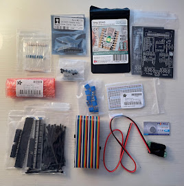
The final soldering task for this telescope is by far the most complicated: building the custom circuit board. Dr. Proffen and I had to attach a multitude of pieces to a blank board to cover everything the telescope would need; there were 24 different parts in total! Here's what we used:

  • 1 10K Ohm resistor
  • 1 680 Ohm resistor
  • 3 47uF capacitors
  • 1 transistor 
  • 5 blue terminal blocks
  • 2 stepper motor drivers (+ heatsinks)
  • tiny2040
  • pin headers
  • 40way PCB header
  • 40way rainbow ribbon cable

That's... quite a lot of pieces, so let's break it down as past me solders them all onto the circuit board. Starting with the resistors: they decrease the voltage of electrical currents so that certain parts don't get fried from too much power. The capacitors act like a reserve battery, but much faster. If there were a sudden power surge, the capacitors would hopefully keep everything from going crazy. Since the tiny2040 doesn't have an on/off switch, we use the transistor to tell it when to have the power on. The blue terminal blocks allow us to make connections between the stepper motor drivers and the rest of the telescope. We could connect directly to the drivers, but in the case of a faulty piece, this is a much easier setup.

We need our 2 stepper motor drivers from before; we added heatsinks on to make sure they don't overheat. Our tiny2040 also gets added, along with some pin headers for a GPS component. Finally, we soldered on a 40-way set of pin headers, which took forever!! Once this was on, we could connect our absolutely beautiful rainbow ribbon cable from these headers to our Raspberry Pi.

Wrapping up

Phew, we did it! Soldering was a new but super fun experience. I love doing hands-on electronics work, so I had a great time. Building a circuit board is something to be incredibly proud of; it's probably the most complex STEM thing I've ever done! Keep an eye out for the final blogpost of Session 2–preparing the Raspberry Pi. Thanks for reading!

Thursday, February 22, 2024

Telescope Session 2 - Building the base

Hey again! This is Part 1 of the second telescope building session. There will be 3 parts to this session spread over 3 different posts. In this session, we're building the base for the telescope, learning how to solder, and preparing our Raspberry Pi. Lazy susans, molten metal, and star charts galore!

Building the base
Source: Wikipedia
Today's main goal is to build the base for the telescope. When it's finished, the telescope will have two degrees of freedom (ways in which an object can rotate). The first is on the z-axis, around a lazy susan in the base. This is the one we will build today. The second, which I'll get to in a future post, rotates on the y-axis. This second degree of freedom takes the form of a camera tower to sweep the skies above.

The base of the telescope is built almost completely out of 3D printed parts. We will need:
  • main base
  • lazy susan ring
  • 4 M4x20 screws
  • 4 M4 washers
  • 4 M4 locknuts
  • 3 3D printed feet for the base
  • 3D printed wheel with metal axle
To allow the telescope to rotate from left to right, we need to use a lazy susan. Eventually, we will install a stepper motor to turn the telescope on the lazy susan so that the camera has full viewing access to all the stars in the sky. 

To start, we'll put the lazy susan into our base. Notice that it has an outer and inner circle, both of which rotate independently. By using the 4 M4x20 screws to fasten the outer circle to the base, we can use the inner circle to rotate our telescope. Line up the outer circle of the lazy susan with 4 holes in the telescope base. Coming from the top, place the 4 screws into the holes and secure underneath the base with washers and locknuts. 

At this point, we can place our 3D printed wheel into the base. It should follow the ridged track inside the base, and will eventually be powered by a stepper motor. We can also screw in the 3 feet that will raise the telescope slightly and stabilize it. There are 3 holes evenly spaced on the base where the feet go.

Adding the rotating platform
Now that we have installed our lazy susan, we can build the rotating platform that the rest of the telescope will sit on. This is the section that will be directly attached to the inner circle of the lazy susan. To do this, we will need:
  • 10 wedge-shaped 3D printed pieces
  • 1 larger 3D printed wedge
  • 5 M4 locknuts
  • 4 small 3D printed inserts
  • 1 blue 3D printed insert
  • 24 3D printed dowels
First, we need to assemble the platform that will be attached to the lazy susan. For this, we will need the wedge-shaped pieces, the inserts, and all the dowels. To secure the platform to the base later, we will need to use screws and locknuts. The locknuts need a place to rest, so we put the black inserts into the space in the top of 4 wedges. Place a locknut into each hexagonal hole in the inserts.

Our last insert is the blue one, which goes in a special place. It will be used later for rotating the telescope, and we need to slot it into a hole on the side of one of our wedges. Choose a wedge with a black insert, place your final locknut in the blue inserts' recess, and be prepared to do a lot of sanding. I ended up getting my insert halfway in and resorting to brute force for the rest of it. When the insert is in place, the hole in the locknut should line up with the hole running through the wedge. 

Now we can assemble the platform. Take the larger wedge and place two dowels into its side; one at the top and one at the bottom. Then snap the wedge with the blue insert onto the dowels. Continue this process until a full circle is completed. Make sure that the wedges with black inserts are placed across from each other, so that they are spread out evenly in the circle. 

Putting it all together
The final step for building our base is to attach the rotating platform onto the lazy susan. We will need:
  • 4 M4x20 screws
  • our base, with the lazy susan
  • circular 3D printed platform
Place the platform on top of the lazy susan, and line up the 4 wedges with inserts with 4 holes on the inner circle of the lazy susan. Make sure that the wheel and axle goes through the large hole in the big platform wedge. Then, coming from the bottom of the base, secure the platform to the lazy susan with 4 screws through the black inserts. Tighten the screws with the locknuts.

Woohoo, we've built the base for our telescope!! In the end, it should look like the photo. The platform should rotate smoothly when pushed, and the axle of our wheel should stick up from the large wedge in the platform. Thanks for reading, and keep and eye out for part 2 of this session!

Sunday, February 11, 2024

Telescope - Materials

Hey there! Welcome to the first in a group of long-term posts. This post will kick off a multi-month technology journey: building a telescope!

My mentor, Dr. Proffen, and I are building a fully functioning telescope together. It'll be about the size of a dinner plate, fully coded and able to capture images and rotate to find stars and constellations. Building this is going to be a long process, so I hope you stick around :) This will be the hardest project I've ever done, but I'm super excited for it!

As of right now, we have all our materials ready for the fun to begin. This telescope is mainly made out of 3D printed parts, technology, and lots of metal fasteners. In total, there are 247 3D printed parts in one telescope. Dr. Proffen printed all of the pieces himself, and shipped my set to me. Now that I have everything, let's do some unboxing!

This project was developed by: MattHh on Autodesk Instructables -- https://www.instructables.com/Pi-lomar-3D-Printed-Working-Miniature-Observatory-/

3D printed pieces
3D printed parts make up most of the telescope. We will need to build a base, a tower for the camera to sit on, and the dome that keeps everything contained. Each piece was wrapped in bubble wrap, so it took a long time to unbox this part ;) 


The black parts make up the base and camera tower for the telescope. We'll build everything on top of the circular base, which rotates using the lazy susan in the image. All of the other parts will sit on top so the telescope and rotate to capture images in all directions.


The dome is made out of white plastic, mostly to provide a contrast in the design of the telescope. When everything is put together, it will look like a miniaturized observatory! We have parts for the round dome, the opening where the camera looks out, and some extra pieces to represent an open observatory door.

Tools/Electronics
There's a crazy amount of electronics required for this telescope. The system is programmed with a Raspberry Pi 4, connected to a camera to capture images and 2 stepper motors to rotate the camera. I'll go into more detail on what each piece does as we move through the process.

In addition, we need lots of tools to make our telescope function as well as possible. Among other things, I have a wrench set; sandpaper and a filing kit; a soldering iron; wire cutters; power adapters; and more nuts, bolts, and screws that I know what to do with (all organized of course).


Hardware
Surprise: there's more hardware! In addition to computers and motors, we need things like breadboards to solder with, ribbon cables, and resistors. The telescope requires a tiny2040 microcontroller, as well as a GPS module to be able to track our coordinates in case we take the telescope places. Fun fact: I now own the biggest ribbon cable I have ever seen ;)

Other Parts
Finally, we need some other small construction pieces to finish off our materials list. Among these are 3D printed dowels of varying sizes, silicone adhesive, fun circular levels, and gears to rotate our telescope.

Putting it all away
All of these parts came in 3 big boxes, and I had to fit them into one massive tub. It likely took around an hour and a half to sort through it all, but now everything is organized and ready for building!

Next steps
Now we can finally get on to building the telescope! I've downloaded the required materials for configuring the Raspberry Pi, so our next step is to start constructing the base of the telescope. Keep an eye out for the next post on this journey :) See you all soon!

Friday, February 2, 2024

Fun Fact! - Question Mark?

Heyo! Here's a quick fun fact about how The Question Mark in Space got its name:)

You might be wondering, "How did she come up with 'The Question Mark in Space' as a blog name?" It is a seemingly random name, but there's most definitely a reason behind it. Luckily, you have a space nerd to tell you all about it.

This blog's name came from a discovery made by the James Webb Space Telescope released by NASA in July 2023. Through images the sent back by JWST, researchers found a formation in space resembling the shape of a question mark! There's been speculation of aliens, a glitch in the Matrix, and the possibility of the Doctor from Doctor Who reaching out to us (my personal favorite), but scientists aren't really sure what this cosmic punctuation is.


We've captured images containing question mark-like shapes in the universe before, with the Hubble Space Telescope. In 2008, the telescope snapped an image of 2 galaxies merging in a vaguely question mark-like shape. In 2009, another image was taken of 4 galaxies which created an optical illusion to look like a question mark.

According to Matt Caplan of Illinois State University, “The very first thing you can rule out is that it’s a star in the Milky Way.” From its color, the formation is likely occurring billions of light years from Earth. Various scientists have lots of theories, ranging from a "right place, right time" optical illusion to a distorted spiral galaxy merging with another.

Overall, finding punctuation in space is pretty epic, and seemed like the perfect name for a space blog! After all, the goal is to find answers and discover new and exciting things :)

See you soon!

Katie 🌈

Resource for scientific info & image: Smithsonian Magazine - Margaret Osborne

Telescope Session 2 - Learning to solder!

I'm back again for more telescope fun! This is Part 2 of my second telescope building session, where I learn how to solder :) For this t...